
- English
- Español
- Português
- русский
- Français
- 日本語
- Deutsch
- tiếng Việt
- Italiano
- Nederlands
- ภาษาไทย
- Polski
- 한국어
- Svenska
- magyar
- Malay
- বাংলা ভাষার
- Dansk
- Suomi
- हिन्दी
- Pilipino
- Türkçe
- Gaeilge
- العربية
- Indonesia
- Norsk
- تمل
- český
- ελληνικά
- український
- Javanese
- فارسی
- தமிழ்
- తెలుగు
- नेपाली
- Burmese
- български
- ລາວ
- Latine
- Қазақша
- Euskal
- Azərbaycan
- Slovenský jazyk
- Македонски
- Lietuvos
- Eesti Keel
- Română
- Slovenski
- मराठी
- Srpski језик

Antenna gain and beamforming
1. Antenna gain
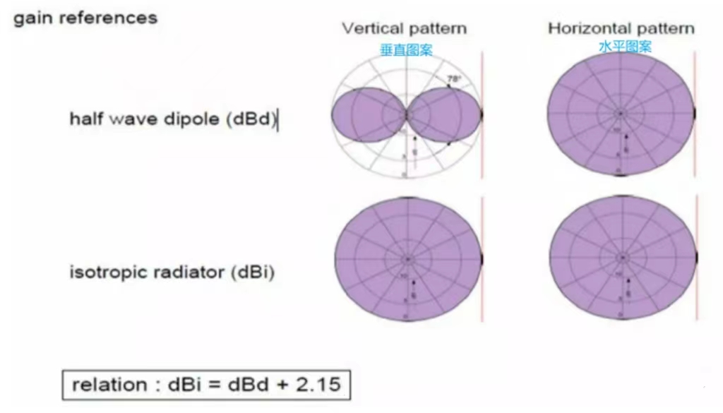
Antenna gain is a parameter to measure the directivity of antenna radiation pattern. High-gain antennas will preferentially radiate signals in specific directions. The gain of the antenna is a passive phenomenon in which power is not added by the antenna, but is simply redistributed to provide more radiated power in one direction than the other isotropic antennas emit. Gain is measured in dBi and dBd:
1) dBi: reference isotropic antenna gain;
2) dBd: refer to the gain of the dipole antenna.
In practical engineering, a half-wave dipole is used instead of an isotropic radiator as a reference. The gain (dB on the dipole) is then given in dBd. The relationship between dBd and dBi is given below:
dBi = dBd + 2.15
Antenna designers must consider the specific application characteristics of the antenna when determining the gain:
1) High-gain antennas have the advantages of longer range and better signal quality, but must be aligned in a specific direction;
2) The range range of low-gain antennas is short, but the direction of the antenna is relatively large.
2. Beamforming
2.1 Principle and application
Beamforming (also known as beamforming or spatial filtering) is a signal processing technique that uses sensor arrays to send and receive signals in a directional manner. By adjusting the parameters of the basic elements of the phase array, the beamforming technique makes the signals of some angles obtain the interference of the phase, and the signals of other angles obtain the interference of the elimination. Beamforming can be used at both the transmitting end and the receiving end of the signal. Simple understanding can be peak to peak, peak to trough, which will increase the gain of the peak to the peak direction.
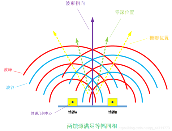
Beamforming is now widely used in 5G antenna arrays, antennas are passive devices, and 5G active antennas refer to high-gain beamforming. The gain of the two point sources in normal equiphase is 3dB, and the antenna port of 5G is greater than 64, so how much is the gain of 5G directivity. A great feature of beamforming is that the direction of the beamforming changes as the phase changes, so it can be adjusted according to demand.

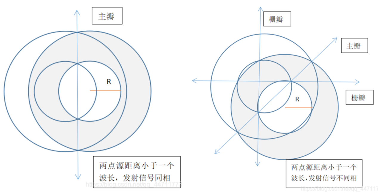
As can be seen from the first figure, when the main lobe is generated, a grid lobe with many peaks superimposed will also be generated. The amplitude of the grid lobe is equal to that of the main lobe, which will reduce the gain of the main lobe, which is unfavorable to the antenna system. So how to remove the grating lobe, in fact, we know the root cause of beamforming ---- phase. As long as the distance between the two feeders is less than one wavelength, and the feeders are in constant amplitude and in phase, the gate lobe will not appear. Then, when the feeders are in different phases and the feed-distance is less than one wavelength and more than half wavelength, whether a gate lobe is generated is determined by the phase deviation degree. When the feed distance is less than half a wavelength, no gate lobe is generated. It can be understood from the diagram below.
2.2 Advantages of beamforming
Compare two antenna systems and assume that the total energy emitted by both antennas is exactly the same.
In case 1, the antenna system radiates almost the same amount of energy in all directions. The three UeS (User Equipment) around the antenna will receive almost the same amount of energy, but waste most of the energy that is not directed to those UEs.
In case 2, the signal strength of the radiation pattern (" beam ") is specifically "formed" so that the radiated energy directed towards the UE is stronger than it is not directed towards the rest of the UE.

For example, in 5G communication, by adjusting the amplitude and phase (weight) of the signals transmitted by different antenna units, even if their propagation paths are different, as long as the phase is the same when reaching the mobile phone, the result of signal superposition enhancement can be achieved, which is equivalent to the antenna array aiming the signal at the mobile phone. As shown in the picture below:

2.3 Beam "Forming"
The simplest way to form a beam is to arrange multiple antennas into an array. There are many ways to align these antenna elements, but one of the easiest is to align the antennas along a line, as shown in the following example.
Note: This example diagram was created by the Matlab PhaseArrayAntenna toolbox.
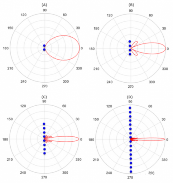
Another way to arrange the elements in an array is to arrange the elements in a two-dimensional square, as shown in the following example.
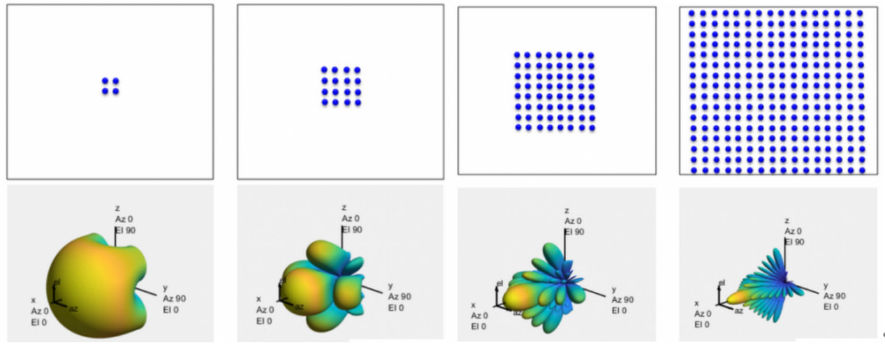
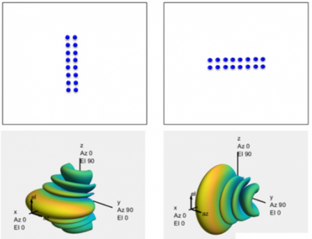
Now consider another two-dimensional array where the shape of the array is not a square, as shown below. The intuition you can get is that the beam compresses more along the axis of more elements.
2.4 Beamforming technology
There are several different ways to achieve beamforming:
1) Switching array antennas: This is a technique for changing the beam pattern (form of radiation) by selectively opening/closing antennas from the array of an antenna system.
2) DSP-based phase processing: This is a technique to change the beam orientation pattern (form of radiation) by changing the phase of the signal passing through each antenna. With a DSP, you can vary the signal phase of each antenna port to form a specific beam orientation pattern that works best for one or more specific UEs.
3) Beamforming by precoding: This is a technique that changes the beam orientation pattern (radiation form) by applying a specific precoding matrix.
Previous:Portable Drone Jammer's advantage